Plan 25
1840 · General Plan · Work 493 of 1,871
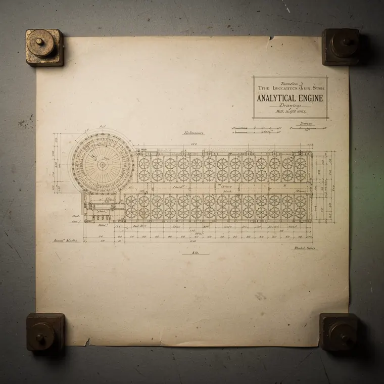
The largest of the Analytical Engine drawings, an enormous sheet of cream paper filling the frame, an ink plan of mill and store together, the circular mill at one end and the long ranks of the store stretching away from it, hundreds of gear columns drawn as rings of circles laid out in rows like a factory floor, ruled dimension lines, the title block a plain ruled box, the sheet laid flat on a grey studio table, even flat light from directly above.
- What it was used for
- Plan 25 is a drawing, not a device: sheet BAB/A/089/1 of the Babbage Papers at the Science Museum, dated 6 August 1840, 61 by 92 centimetres, titled "The general plan of Mr. Babbage's Great Calculating Engine. Arrangement and rack, details, et cetera." Plans of this kind show the machine from above and set out the sub-assemblies in relation to one another; the Computer History Museum describes them as micro-architecture diagrams. Plan 25 was the state Babbage explained at Turin in 1840. Menabrea then wrote his sketch of the engine (Bibliothèque Universelle de Genève, October 1842), which Ada Lovelace translated with her notes in 1843.
- What was new
- What was new about Plan 25 was not the machine but the fact that this plan left the workshop: the Computer History Museum records that Babbage had it engraved for printing. Through Menabrea and Lovelace this state became the version the world knew. The barb: Babbage had already moved past it. After Plan 27 he went to Plan 28, mechanically a great deal simpler but at the cost of performance - and out of that work came Difference Engine No. 2. The series of Analytical Engine drawings runs to 183 sheets from September 1834 to 6 March 1849, with about 30 plans. One of them is well known.
Further reading
- Science Museum Group, The Babbage Papers: The general plan of Mr. Babbage's Great Calculating Engine (Plan 25), BAB/A/089/1
- Science Museum Group, The Babbage Papers: Drawings of the Analytical Engine (BAB/A)
- Computer History Museum: The Analytical Engine - 28 Plans and Counting
- L. F. Menabrea: Sketch of the Analytical Engine (Bibliothèque Universelle de Genève, Oktober 1842, Nr. 82), mit Notes von Ada Lovelace - Fourmilab