Centrifugal Governor
1788 · Control Engineering · Work 93 of 1,871
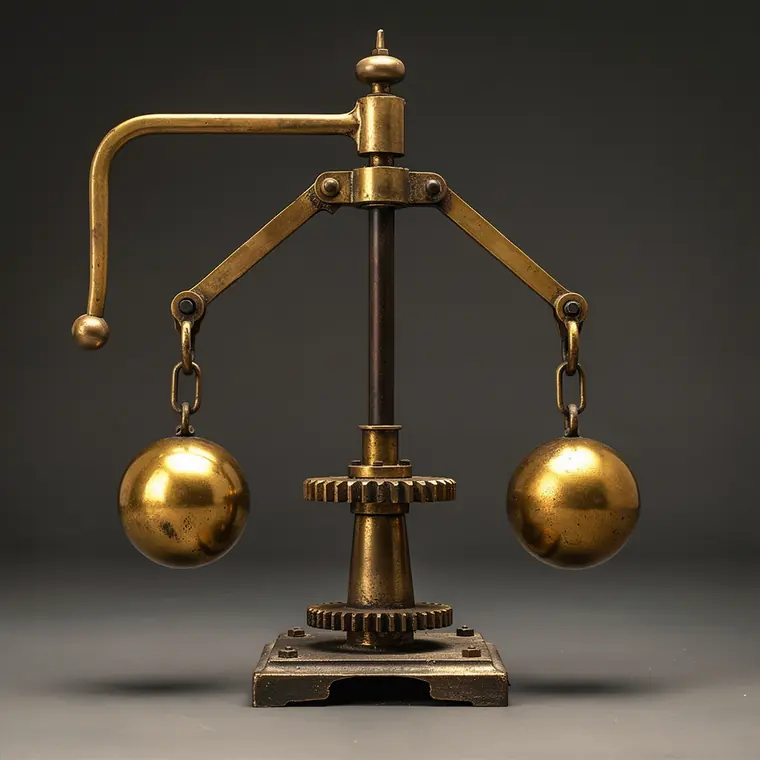
A centrifugal governor in close view: an upright spindle turned by bevel gears at its foot, two arms hinged at the top of the spindle hanging down on either side, a heavy brass ball at the lower end of each arm, the balls swung outward and upward by the spinning, two short links running from the arms down to a sleeve that slides on the spindle, the sleeve lifted as the balls fly out, a lever resting on the sleeve and the throttle linkage running away from it to the steam valve, the balls free on hinged arms.
- What it was used for
- The centrifugal governor keeps the speed of a rotative steam engine nearly constant when load or steam supply varies. It acts on the throttle valve. The first engine fitted with one was the Lap Engine of 1788, built for Matthew Boulton's own Soho Manufactory in Birmingham, where it drove 43 metal-polishing machines for seventy years. The dating is not uniform: a scholarly account gives November 1788 for the design and early 1789 for first use. Boulton and Watt never patented the governor. The reason lies with Watt himself: he judged it no invention at all, merely an adaptation of a millwright's device.
- What was new
- Centrifugal pendulums were long familiar to millwrights. The lift-tenter regulated the gap between millstones in wind and water mills, that is, the fineness of the flour. What was new was not the mechanism but where it acted: Watt's governor intervened not in the process but in the supply of power. A governor patent by Thomas Mead is held by the Mills Archive. The cost of the design was inherent and stayed so: the governor is purely proportional and therefore holds the set speed exactly at only one operating point - critics called it a moderator, not a controller. From the early nineteenth century came reports of governors hunting. Maxwell's answer was "On Governors", Proceedings of the Royal Society 16 (1868), pp. 270-283.
Further reading
- Science Museum Group: Rotative Steam Engine by Boulton and Watt, 1788 (Lap Engine)
- Otto Mayr, Feedback Mechanisms in the Historical Collections of the NMHT, Smithsonian Studies in History and Technology 12 (1971)
- Stuart Bennett, A Brief History of Automatic Control, IEEE Control Systems Magazine, Juni 1996, S. 17-25
- J. C. Maxwell, On Governors, Proc. R. Soc. London 16 (1868) 270-283